Modeler
For advanced editing of the atomic structure, click Modeler from the menu  in the lower left corner to open modeler view.
You can utilize modeling functions from the right-side panel, and you have the flexibility to apply functions one after another as needed.
Changes made in modeler are applied to the project by clicking Reflect on Input-file. If you wish to return to the state before any editing was done (the state when the modeler view was initially opened), you can click Initialize Model .
After completing the editing, click the back button  in the lower left corner to return to the project view.
Autopilot
This is a feature that utilizes ChatGPT to create models based on natural language instructions. Clicking the Autopilot button  in the bottom right corner of the modeler screen will display an input field for entering instructions.

Enter the description of the model you want to create. You can also use voice input with the  button. Submit with the
  button. Return to the previous screen with the
  button.
Examples of instructions
“The solid-liquid interface between the 110 surface of NMC electrode and 1 mol/L LiBF4 in EC:DMC (7:3) solution”
Create a supercell of layered LiCoO2:sub:, substitute Co with Mn and Ni and create a (110) slab, then pack EC, DMC, Li+, and BF4-in the specified ratio.
⸺ AI will model with an understanding of what an NMC electrode means.
“An alloy with Fe/Ni/Cr/Mn ratio = 7/1/1/1”
Create a supercell of Fe, then substitute 10.0% of Fe with Ni, 11.1% of Fe with Cr, and 12.5% of Fe with Mn.
⸺ AI will automatically calculate the element substitution rates.
“ZrO2(001)/Rh(111) + 2 x NO@hollow”
Create an interface model of ZrO2:sub:(001) and Rh(111), then adsorb two nitric oxide molecules on hollow sites on top of it.
⸺ AI understands ambiguous expressions using chemical formulas as well.
When the instruction is interpreted, the corresponding modeler operation steps are displayed. Clicking Run will execute these steps.
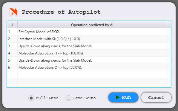
Full-Auto
All steps are automatically executed and the model is created without any user intervention.
Semi-Auto
An explanation is shown at each step, guiding the user through the operations. This is useful when you want to manually set details such as parameters.
When the arrow in the bottom left turns red
, click it to proceed to the next step.
Note
This feature requires an internet connection as it is executed by connecting to an external server.
Note
A daily limit is set for sending instructions and voice input, respectively. When the limit is reached, the function will be unavailable for the rest of the day.
Click on the icon  located in the upper left corner of the screen, and open to open the setting dialog. You can also check the terms of use and change the setting to allow the use of instructional text for product development here.
Translation
Utilize the Translation of Cell function in the Cell tab to move all atoms in the same direction and distance. The changes made to the vector sliders will be immediately reflected in the viewer in real-time.
Super cell
To construct a super cell with a repeating unit cell structure, navigate to the Cell tab and use Super Cell function. Enter the desired repeat counts along a, b, c axes into the three text boxes in the Scaling field, and then click Build.

Non-diagonal super cell expansion
To create a more general super cell, not limited to repeating along the axes but including the redefinition of the lattice vectors, utilize the Super Lattice function in Lattice tab.
As Miller Index : specify the destination of each lattice vector using Miller indices (i.e. enter the transformation matrix for lattice vectors).
As Dual Vector : calculate the smallest integer ratio that is equal to the reciprocal ratio of the entered values and use it as the Miller indices.
Since each element of the transformation matrix is an integer, the transformed lattice once again becomes a unit lattice.

Edit lattice vectors
To edit the lattice vector, use the Lattice Vectors function in the Lattice tab.
Affine Positions : atom coordinates are converted along with the lattice transformation.
Leave Positions : atom coordinates remain unchanged.
Select Refine to adjust the lattice vectors, ensuring they are compatible for Bravais lattice representation in Quantum ESPRESSO.
Positions of Atoms
Select the atom(s) whose positions you wish to adjust, and then click Start Modeling in the Atom tab.
Move the atoms(s) along the coordinate axes using the ΔX(ΔY, ΔZ) / Angs. sliders. Alternatively, You can input the value directly through the Input directly option in the right-click menu.
Utilize X(Y, Z)-Mobility feature to fix / unfix atom(s) along the coordinate axes. This setting is applied for structural optimization or molecular dynamics calculations.
Rotate the atoms around their geometric center using the Rotationtool. When you click the Rotate Atoms, a sphere appears, then drag this sphere to rotate the atoms. Press Esc to set their position.
Conversion of crystal lattice
Redefine the model’s lattice vector to transform the crystal lattice.
In the Crystal tab, click the corresponding Build button to perform the conversion.
Finding a Primitive Cell
- Finding a Standard Cell
automatically find and convert to primitive / standard cell.

- More Symmetric Cell
Discover a more symmetric crystal structure, permitting some variation in atom locations. You can specify the tolerance threshold using the
 button.
Hexagonal -> Orthorhombic
- Orthorhombic -> Hexagonal
Transform into hexagonal crystal / orthorhombic crystal.

Additionally, by using the Operation for Axis buttons in the Cell tab, you can flip / swap the lattice vectors.
Element substitution
Replace certain atoms in the model for different types of atoms.
In the Crystal tab, click Start Modeling under Element Substitution to display the element substitution view.
Set the Element to be Substituted, For What Element ?, Super Cell (specify the repeating number for creating super cell), and the Rate of Substitution sequentially. Use the Next ( Previous ) buttons to navigate through these options. Once finished, click Build to display the post-substitution structure in the viewer, including its symmetry. Clicking Build again will show a different structure with the same substitution settings.
Click the back button locatded at the lower left to return to modeler view.
Point defect (vacancy)
Remove atoms from the model to create point defects (vacancies).
In the Crystal tab, click on Start Modeling under Lattice Defect to access the lattice defect view.
Firstly, set the Element to be Removed, the Super Cell (enter the repeating number if creating super cell), and the Rate of Lattice Defect sequentially. Use the Next ( Previous ) button to navigate through the next (previous) item. After completing these steps, click Build to display the structure with the defects in the viewer, including symmetry. Clicking Build again will show a different structure, but with the same defect setting.
Click the back button locatded at the lower left to return to modeler view.
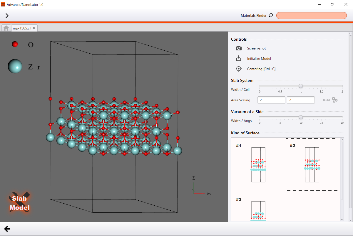
Slab model
Build a model for slab approximation, where non-periodic systems like surfaces are approximated using periodic boundary conditions.
In the Slab tab, specify a crystal plane as the surface using Miller indices, then click Build. This action will display a detailed view of the slab model settings.
Adjust the slab’s thickness by modifying Width / Cell in the Slab System section, and set the vacuum layer’s thickness using Width / Angs. in the Vacuum of a Sidesection. To create a repeated structure along the in-plane direction of the slab, enter the repeat count in the text boxes under Area Scaling and then click Build.
If multiple different surface atomic structures exist, select your preferred option from the list of candidates displayed under Kind of Surface.
Modifications are updated and displayed in the viewer in real-time.
Click Initialize Model to revert to the state prior to detailed settings being applied (as it was when the slab model view was first opened).
Click the back button locatded at the lower left to return to modeler view.
Once the slab model is built, additional modifications can be made using the Editing Slab Model buttons.
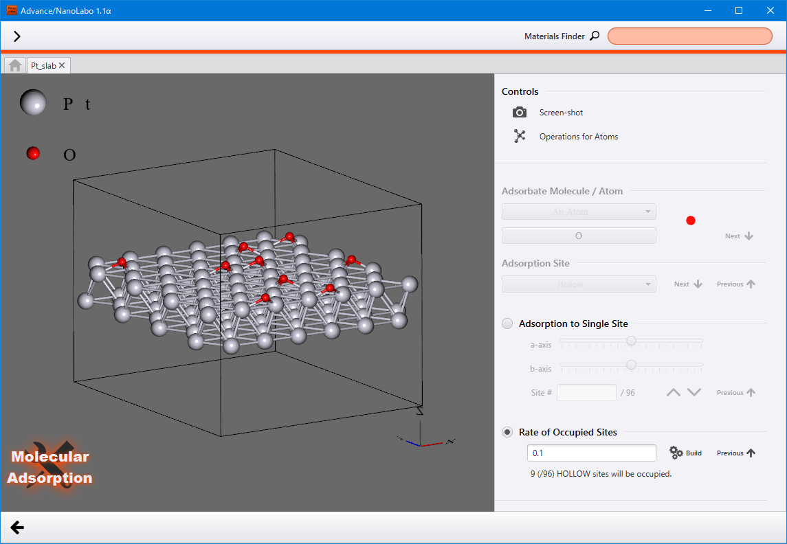
Molecules adsorption
Adsorb molecules onto the slab model.
Prepare a slab model and select the Slab tab. Then click on Start Modeling under Molecular Adsorption onto Slab to display the view of molecules adsorbing onto the slab.
Set the Adsorbate Molecule / Atom and select the Adsorption Site. To navigate through the items, click Next ( Previous ) to move forward (go back) .
Adsorbate Molecule selection includes predefined options. Additionally, you can import custom molecules by selecting from the main menu
located at the top-left.
There are two types of adsorption methods available: Adsorption to Single Site and Rate of Occupied Sites. Please choose the one you would like to use.
Adsorption to Single Site : adjust the position along the a/b axis by using the sliders, or specify the site by using the serial number assigned to each site.
Rate of Occupied Sites : input the occupation rate and click Build to display the structure with adsorbed molecules in the viewer. Clicking Build again will show a different structure while maintaining the same settings.
Click the back button locatded at the lower left to return to modeler view.
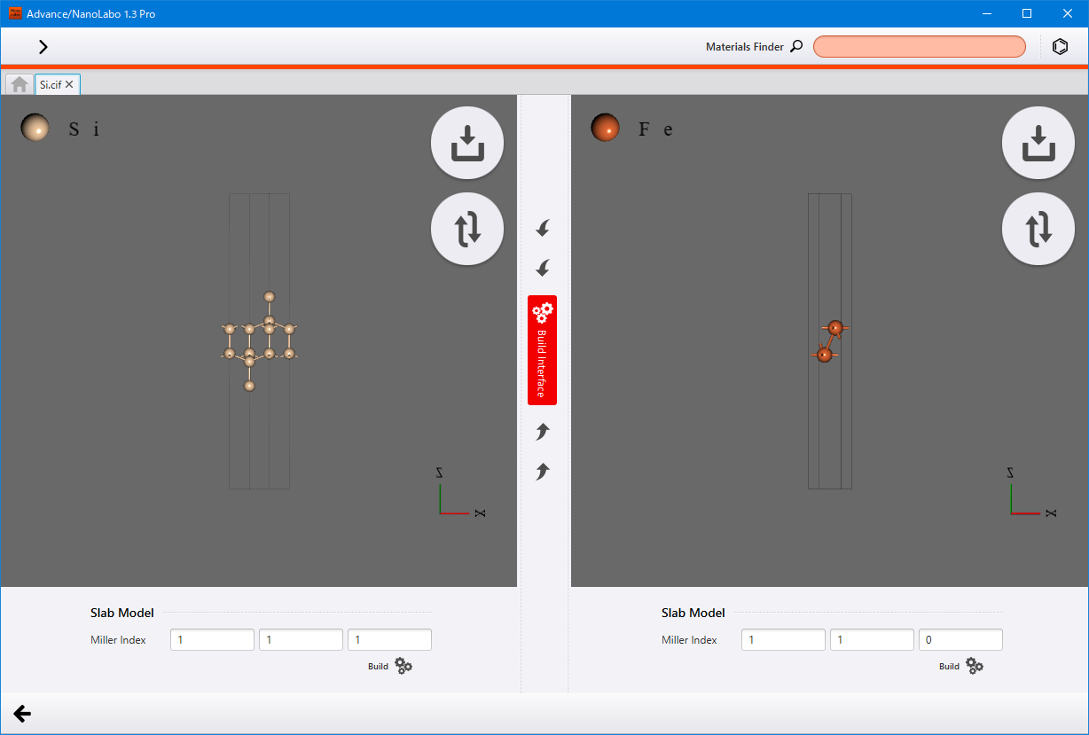
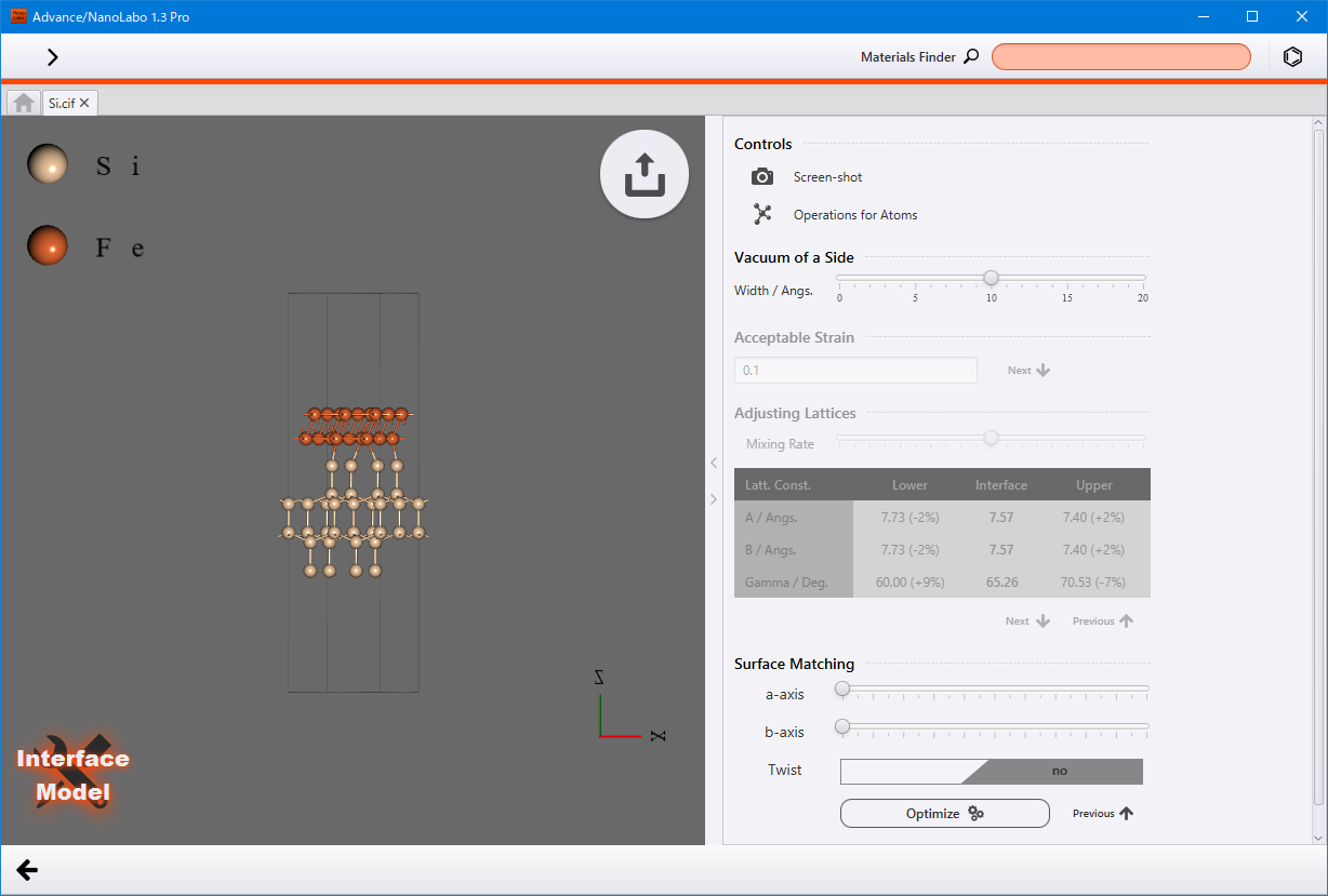
Interface model (Pro version only)
Construct an interface model by combining two crystal models that have different lattice constants.
In the Slab tab, click on Start Modeling under Interface Model to display the interface model view.
Begin by creating two slab models. First, for the left-hand side model, specify the crystal plane to be the surface using the Miller Index and then click Build to create a slab model. Next, click the import button  located at the upper right. In the explorer view, double-click on the model to be used for the second one. Once this model appears on the right-hand side, input the Miller indices and create another slab model following the the same way.
Click the Build Interface button in the middle to proceed to build interface view.
Enter the Acceptable Strain value and click Next to search for the interface. Review the result, and if it is satisfactory, click Nextagain. You can adjust the position along the a/b-axis using the sliders. To optimize the inter-slab distance with classical force field, click Optimize.
Click the finish modeling button  located at the upper right corner of the viewer. This will fix the structure and return to modeler view.
Drawing a molecule
You can use the molecular editor JSME to draw a structure and use the structure as a model.
In the Molecule tab, click on Start Modeling under Drawing a Molecule to access the view for drawing a molecule. The molecule editor is displayed on the left side, and the 3D model appears on the right side. The structure that you created on the editor will be displayed as 3D model in real time.
For guidance on using the editer, please refer to JSME Help documentation.
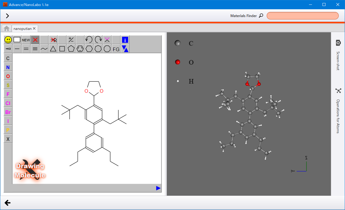
Click the back button located at the lower left corner to return to the modeler view. Be aware that the previous model will be overwritten.
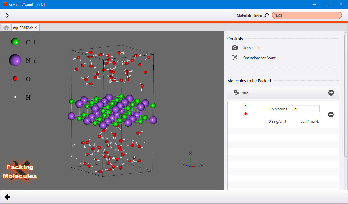
Packing molecules
Pack small molecules into the empty space in the model.
Prepare a model that has sufficient space for packing molecules. Then, in the Crystal tab, click on Start Modeling under Packing Molecules to access the view for packing molecules.
On the right side panel, configure the molecules and their quantity in the Molecules to be Packed. Initially, water is present in the molecules list.
Click the
 button to add a molecule to the list. In the explorer view, double-click on the molecule you wish to use. You can also utilize the Materials Finder to search the molecule. Once the molecule is added to the list, specify the quantity of this molecule to be packed.
Click the
 button on the right to delete the molecule from the list.
Once finished, click Build to display the structure with packed molecules in the viewer. If you click Build again , a different structure will bw shown, but with the same settings retained.
You can also perform packing by specifying the density using Resize Cell by Density. If there are multiple types of molecules in the list, it will be the total density.
For molecular models: Creates a cubic cell. After Resize, clicking Build will create a model with the specified density.
For slab models: Adjusts the thickness of the vacuum layer. After Resize, clicking Build will fill the vacuum layer with molecules at the specified density.
Click the back button locatded at the lower left to return to modeler view.
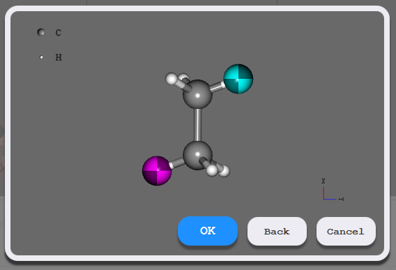
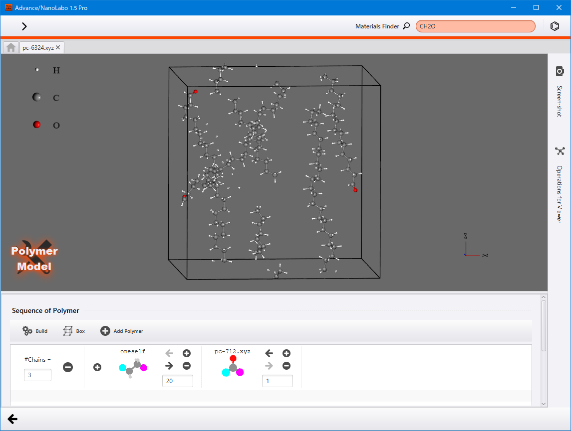
Polymer modeler (Pro version only)
Generate a polymer model from the monomer model and then pack it into the designated space.
Prepare a monomer model. In the Molecule tab, click on Start Modeling under Polymer Model to access the polymer modeler view.
First, specify the size of the space for filling polymers in the dialog. Then, on the displayed monomer model, double-click to select the head side atom for polymerization and click OK. Similarly, select the tail side atom for polymerization in the same way.
After making your selections, a row will be added to the Sequence of Polymer section at the bottom. Enter the degree of polymerization in the the designated field located on the lower right of oneself, and input the number of polymer chains in the #Chains field.
You have the option to pack various types of polymers simultaneously. To add a different polymer, click Add Polymer, select a monomer, and then proceed with the settings. If you need to remove a polymer, click the button located at the right of the #Chains field.
Furthermore, you can attach another polymer to the head (tail) by clicking the button on the left (right) side of the monomer box. To remove the polymer from the box, click button. You can also change the order of the polymers using the arrow buttons.
To modify the dimension of the space, click the  button. Input the size along the XYZ directions in Å units. Then, click the icon to apply these changes.
Once you have completed the polymer settings, click Build to display the structure with the packed molecules in the viewer. Clicking Build again will present a different structure while maintaining the same settings.
Click the back button locatded at the lower left to return to modeler view.
Additionally, you can pack polymers into areas like vacuum layer of the slab model. Ensure that your model has sufficient space for packing polymers. Once your model is prepared, open the polymer modeler within that project. Polymers that are added using the Add Polymer will be packed into the empty space within the model.